Indicate Whether The Drawing Is Orthographic Isometric Or Perspective
Onlines
Apr 01, 2025 · 6 min read
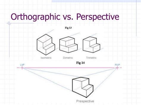
Table of Contents
Indicating Whether a Drawing is Orthographic, Isometric, or Perspective
Identifying the type of projection used in a technical drawing is crucial for understanding the information it conveys. Three primary projection methods dominate engineering, design, and architecture: orthographic, isometric, and perspective. Each offers a distinct way of representing three-dimensional objects on a two-dimensional plane, each with its own strengths and limitations. This comprehensive guide will equip you with the skills to confidently distinguish between orthographic, isometric, and perspective drawings.
Understanding the Three Main Projection Methods
Before diving into the identification process, let's solidify our understanding of each projection type.
Orthographic Projection
Orthographic projection is the cornerstone of technical drawing. It utilizes multiple views – typically front, top, and side – to represent an object's complete shape and dimensions. Each view shows the object as seen from a specific direction, perpendicular to the projection plane. Imagine looking directly at each face of a cube; each view would be a separate orthographic projection.
Key Characteristics of Orthographic Projections:
- Multiple Views: Uses at least two, often three or more, views to completely define the object.
- Parallel Lines: All lines parallel to the projection plane remain parallel in the drawing.
- True Dimensions: Dimensions are accurately represented in the views they are fully visible.
- No Perspective: Lacks the visual cues of depth and perspective found in other projection methods.
- Best for: Detailed, accurate representations of objects, especially for manufacturing and construction.
Isometric Projection
Isometric projection offers a simplified, three-dimensional representation of an object in a single view. It's a type of axonometric projection, meaning it's created by projecting the object onto a plane that's not parallel to any of its faces. The axes (x, y, and z) are equally spaced at 120-degree angles, resulting in an image that's visually easier to grasp than orthographic projections, while still retaining the dimensions of the object, though not always to scale.
Key Characteristics of Isometric Projections:
- Single View: Presents a three-dimensional view of the object in a single drawing.
- Parallel Lines: Parallel lines in the object remain parallel in the drawing.
- Slightly Distorted Dimensions: While dimensions are represented, they aren't perfectly to scale along all axes due to the projection angle. Measuring directly from the drawing might lead to inaccuracies.
- Visual Depth: Provides a better visual understanding of the object's three-dimensional shape compared to orthographic views.
- Best for: Conceptual designs, illustrations, and quick visualization of 3D objects.
Perspective Projection
Perspective projection mimics how the human eye perceives the world. It creates the illusion of depth and distance by converging parallel lines towards a vanishing point on the horizon. This creates a more realistic representation of an object, but it also sacrifices the accurate representation of dimensions. There are different types of perspective drawings including one-point, two-point, and three-point perspective.
Key Characteristics of Perspective Projections:
- Single View: Presents a single, three-dimensional view.
- Converging Lines: Parallel lines appear to converge towards vanishing points.
- Realistic Depth: Provides a strong sense of depth and realism.
- Distorted Dimensions: Dimensions are not accurate and are significantly distorted as they recede into the distance.
- Best for: Architectural renderings, artistic representations, and creating realistic visuals for presentations or marketing materials.
Identifying the Projection Method: A Step-by-Step Guide
Identifying the type of projection used involves carefully examining the characteristics of the drawing. Here's a systematic approach:
Step 1: Count the Number of Views
- Multiple Views (Two or More): This strongly suggests an orthographic projection.
- Single View: Proceed to Step 2.
Step 2: Examine the Lines
- Parallel Lines: If parallel lines in the object remain parallel in the drawing, it's either an orthographic or isometric projection.
- Converging Lines: If parallel lines appear to converge towards a vanishing point, it's a perspective projection.
Step 3: Assess the Sense of Depth and Realism
- Lack of Depth: If the drawing lacks a clear sense of three-dimensionality and relies on multiple views to represent the object, it is likely an orthographic projection.
- Visual Depth, Parallel Lines: If the drawing offers a single view with a three-dimensional appearance, but parallel lines remain parallel, it is likely an isometric projection.
- Realistic Depth, Converging Lines: If the drawing features a realistic sense of depth and distance, with parallel lines converging towards vanishing points, it's a perspective projection.
Step 4: Check for Dimensioning
- Accurate Dimensions: Orthographic drawings are characterized by accurate dimensional notations. While isometric drawings also contain dimensions, they might not be perfectly to scale along all three axes. Perspective drawings usually lack precise dimensional information.
Step 5: Consider the Context
The purpose of the drawing can provide additional clues. Detailed engineering or architectural drawings are more likely to be orthographic. Conceptual designs, illustrations, or artistic renderings might be isometric or perspective.
Examples and Comparisons
Let's consider some examples to solidify our understanding:
Example 1: Orthographic Drawing of a Bolt
An orthographic drawing of a bolt will show separate views (front, top, side) with accurate dimensions for each part of the bolt. Parallel lines will remain parallel in each individual view. The drawing emphasizes precise measurements and details needed for manufacturing.
Example 2: Isometric Drawing of a Cube
An isometric drawing of a cube will show all three dimensions in a single view. All lines representing edges parallel to the coordinate axes will be parallel. However, you won't be able to measure the side lengths with complete precision because of the isometric projection’s inherent distortion. The drawing emphasizes the overall form and spatial relationships of the cube.
Example 3: Perspective Drawing of a Building
A perspective drawing of a building will create a realistic representation of the structure. Parallel lines such as building edges and window lines will converge towards vanishing points. This creates a sense of depth and distance. The exact dimensions of the building cannot be directly measured from the drawing.
Advanced Considerations
While the above steps usually suffice, there are nuanced cases to consider.
- Axonometric Projections (Beyond Isometric): Other types of axonometric projections exist, such as dimetric and trimetric, where the angles between the axes differ from the 120-degree angle of isometric projection. Identifying these requires a more detailed analysis of the angle between the axes.
- Oblique Projection: Oblique projections offer a single view with a combination of parallel and angled lines. Identifying it requires careful observation of how parallel lines are represented.
- Combination of Projection Methods: Some technical drawings might combine different projection types. For example, a drawing might use an isometric view to represent the overall form and then include detailed orthographic sections for specific parts.
By applying these steps systematically and considering the context of the drawing, you can confidently distinguish between orthographic, isometric, and perspective projections, enhancing your understanding of technical drawings and their application in various fields. Mastering this skill is critical for anyone working with visual representations of three-dimensional objects.
Latest Posts
Latest Posts
-
Daniel Piensa Que Los Medios Deben Ser Imparciales
Apr 02, 2025
-
Chapter 6 Summary Of The Pearl
Apr 02, 2025
-
The Author Includes This Excerpt To Establish Gilgamesh As
Apr 02, 2025
-
You Are Dispatched To An Apartment Complex Where A 21
Apr 02, 2025
-
3 4 2 What Is The Probability
Apr 02, 2025
Related Post
Thank you for visiting our website which covers about Indicate Whether The Drawing Is Orthographic Isometric Or Perspective . We hope the information provided has been useful to you. Feel free to contact us if you have any questions or need further assistance. See you next time and don't miss to bookmark.
