Ohm's Law Phet Lab Answer Key
Onlines
Mar 05, 2025 · 6 min read
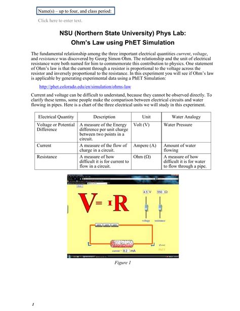
Table of Contents
Ohm's Law Phet Lab: A Comprehensive Guide with Answers
Understanding Ohm's Law is fundamental to grasping the basics of electricity. This law describes the relationship between voltage, current, and resistance in an electrical circuit. The PhET Interactive Simulations Ohm's Law lab provides an excellent, interactive way to explore these concepts. This guide will walk you through the lab, providing explanations, interpretations, and answers to common questions. We'll cover various scenarios, helping you solidify your understanding of Ohm's Law and its applications.
What is Ohm's Law?
Ohm's Law states that the current through a conductor between two points is directly proportional to the voltage across the two points and inversely proportional to the resistance between them. Mathematically, it's represented as:
V = IR
Where:
- V represents voltage (measured in Volts) – the electrical potential difference driving the current.
- I represents current (measured in Amperes) – the flow of electric charge.
- R represents resistance (measured in Ohms) – the opposition to the flow of current.
Navigating the Phet Ohm's Law Lab
The PhET Ohm's Law simulation provides a virtual laboratory environment where you can safely experiment with different circuit components and observe their effects. The interface allows you to adjust voltage, resistance, and observe the resulting current. Key features to familiarize yourself with include:
- Battery: Adjusts the voltage (V) applied to the circuit.
- Resistor: Controls the resistance (R) in the circuit. You can change the resistance value using the slider.
- Ammeter: Measures the current (I) flowing through the circuit.
- Voltmeter: Measures the voltage (V) across the resistor.
Experiment 1: Investigating the Relationship between Voltage and Current (Constant Resistance)
This experiment focuses on understanding the direct proportionality between voltage and current when resistance remains constant.
Procedure:
- Set the resistance (R) to a fixed value (e.g., 10 Ohms).
- Gradually increase the voltage (V) using the battery slider.
- Record the corresponding current (I) readings from the ammeter for each voltage value.
- Plot your data on a graph with voltage (V) on the x-axis and current (I) on the y-axis.
Observations and Answers:
You should observe a linear relationship between voltage and current. As you increase the voltage, the current increases proportionally. The graph will show a straight line passing through the origin (0,0). The slope of this line represents the inverse of the resistance (1/R).
Example Data and Calculations:
| Voltage (V) | Current (I) |
|---|---|
| 1 | 0.1 |
| 2 | 0.2 |
| 3 | 0.3 |
| 4 | 0.4 |
| 5 | 0.5 |
(Assuming a constant resistance of 10 Ohms)
In each case, applying Ohm's Law (V=IR), we can verify the resistance: R = V/I = 10 Ohms consistently.
Experiment 2: Investigating the Relationship between Resistance and Current (Constant Voltage)
This experiment explores the inverse relationship between resistance and current when the voltage is kept constant.
Procedure:
- Set the voltage (V) to a fixed value (e.g., 5 Volts).
- Gradually increase the resistance (R) using the resistor slider.
- Record the corresponding current (I) readings from the ammeter for each resistance value.
- Plot your data on a graph with resistance (R) on the x-axis and current (I) on the y-axis.
Observations and Answers:
You'll observe an inverse relationship. As you increase the resistance, the current decreases. The graph will be a hyperbola, demonstrating the inverse proportionality. The data points will not form a straight line.
Example Data and Calculations:
| Resistance (R) | Current (I) |
|---|---|
| 5 | 1 |
| 10 | 0.5 |
| 15 | 0.33 |
| 20 | 0.25 |
| 25 | 0.2 |
(Assuming a constant voltage of 5 Volts)
Again, using Ohm's Law (V=IR), we can verify the voltage remains constant at approximately 5 Volts for each data point, accounting for minor rounding errors.
Experiment 3: Exploring Different Circuit Configurations (Series and Parallel)
The Phet simulation allows you to explore series and parallel circuits. This is crucial for understanding how resistors combine and affect the overall circuit behavior.
Series Circuits:
In a series circuit, resistors are connected end-to-end. The total resistance (R<sub>total</sub>) is the sum of individual resistances:
R<sub>total</sub> = R<sub>1</sub> + R<sub>2</sub> + R<sub>3</sub> + ...
The current (I) is the same through all resistors. The total voltage (V<sub>total</sub>) is the sum of the voltage drops across each resistor.
Parallel Circuits:
In a parallel circuit, resistors are connected across each other. The total resistance (R<sub>total</sub>) is calculated as:
1/R<sub>total</sub> = 1/R<sub>1</sub> + 1/R<sub>2</sub> + 1/R<sub>3</sub> + ...
The voltage (V) is the same across all resistors. The total current (I<sub>total</sub>) is the sum of the currents through each resistor.
Observations and Answers:
Experiment with different resistor combinations in both series and parallel circuits. Verify that your observations align with the formulas for total resistance and current distribution in each configuration. Note the differences in the total current and voltage across the different setups.
Troubleshooting Common Issues and Addressing Potential Errors:
- Inconsistent readings: Ensure you're accurately reading the ammeter and voltmeter values. Minor variations are expected due to the nature of the simulation, but significant discrepancies suggest a potential error in your setup.
- Unexpected results: Double-check your circuit configuration and ensure you're correctly applying Ohm's Law calculations. Review the formulas for series and parallel circuits to ensure accuracy.
- Difficulty understanding the graphs: Practice plotting the data points and observe the relationships between the variables. A clear understanding of direct and inverse proportionality is key to interpreting the graphs correctly.
Advanced Concepts and Extensions:
Once you've mastered the basics, explore more advanced concepts within the Phet simulation:
- Non-Ohmic materials: The simulation might include components that don't perfectly obey Ohm's Law. Observe how their behavior differs from ideal resistors.
- Power calculations: Calculate the power (P) dissipated by the resistors using the formula: P = IV = I²R = V²/R.
- Circuit analysis: Challenge yourself with more complex circuits involving multiple resistors and voltage sources.
Conclusion:
The Phet Ohm's Law simulation offers a valuable tool for learning and reinforcing your understanding of this fundamental electrical concept. By carefully conducting the experiments, recording data, and analyzing the results, you'll gain a strong grasp of the relationships between voltage, current, and resistance, and how they interact in both simple and complex circuits. This detailed guide provides a structured approach to navigate the simulation, ensuring a thorough understanding of Ohm's Law and its practical applications. Remember to actively engage with the simulation, exploring different scenarios and pushing your understanding beyond the basic exercises. This hands-on approach will solidify your knowledge and build confidence in tackling more complex electrical concepts in the future.
Latest Posts
Latest Posts
-
The Table Shows The Utility A College Student Obtains
Mar 05, 2025
-
A Student Noticed That The Ivy Leaves Growing
Mar 05, 2025
-
Tried Loading Mod With The Same Packageid Multiple Times Calltradeships Kv Rw
Mar 05, 2025
-
Spanish 1b Review Of Unit 1
Mar 05, 2025
-
Mis Hermanos Example Answerse Despiertanend Example Answer Tarde
Mar 05, 2025
Related Post
Thank you for visiting our website which covers about Ohm's Law Phet Lab Answer Key . We hope the information provided has been useful to you. Feel free to contact us if you have any questions or need further assistance. See you next time and don't miss to bookmark.
