3.3.7 Connect Patch Panel Cables 2
Onlines
Mar 26, 2025 · 6 min read
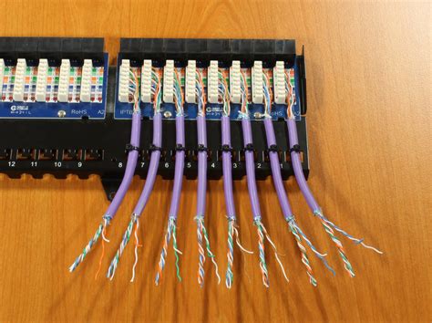
Table of Contents
3.3.7 Connect Patch Panel Cables: A Comprehensive Guide
Patch panels are the unsung heroes of structured cabling systems. They provide a centralized point of termination for cables, allowing for easy management, testing, and reconfiguration of network connections. Understanding how to correctly connect patch panel cables, especially within the context of a 3.3.7 standard, is crucial for ensuring a robust and efficient network infrastructure. This comprehensive guide delves into the specifics of connecting 3.3.7 patch panel cables, covering everything from cable types to troubleshooting common issues.
Understanding the 3.3.7 Patch Panel Standard
The "3.3.7" designation isn't a formal industry standard like TIA/EIA-568. Instead, it likely refers to a specific cabling arrangement or a shorthand notation within a particular company or project. It might represent:
- Three buildings, three floors, seven cable runs: This could imply a network infrastructure spanning multiple buildings and floors with a total of seven cable runs terminating at the patch panel.
- Specific cable length: This is less likely, but "3.3.7" could be a code indicating a particular cable length. Without further context, this interpretation remains speculative.
- Internal company nomenclature: Many organizations use their own internal coding systems for cable management. "3.3.7" could be a unique identifier within such a system.
Therefore, the focus of this guide will be on the general principles and best practices for connecting patch panel cables, irrespective of any specific "3.3.7" coding. These principles are universally applicable across different network infrastructures.
Choosing the Right Patch Panel Cables
Selecting the appropriate patch cables is paramount for optimal network performance and longevity. Several factors influence your choice:
1. Cable Type:
- Shielded Twisted Pair (STP) Cables: Offer superior protection against electromagnetic interference (EMI) and radio frequency interference (RFI), making them ideal for environments with high levels of electrical noise. They are generally more expensive than UTP cables.
- Unshielded Twisted Pair (UTP) Cables: More common and cost-effective than STP cables. While susceptible to interference, they are often sufficient for most office and home network environments. Category 5e (Cat5e), Category 6 (Cat6), and Category 6a (Cat6a) are prevalent choices, with higher categories offering increased bandwidth and reduced crosstalk.
2. Cable Length:
Overly long cables can introduce signal attenuation and degradation, impacting network speed and reliability. It's crucial to use cables of appropriate length, minimizing unnecessary slack while avoiding excessively short cables that may strain connections.
3. Connector Type:
The most common connector type for patch cables is the RJ45 connector. Ensuring the connectors are properly crimped and securely attached to the cables is critical for a reliable connection. Faulty crimping can lead to connectivity problems and data loss.
4. Cable Gauge:
The gauge refers to the thickness of the copper wire within the cable. Lower gauge numbers indicate thicker wires, which offer lower resistance and better signal transmission. Common gauges include 24 AWG and 26 AWG, with 24 AWG generally preferred for longer runs.
Connecting Patch Panel Cables: A Step-by-Step Guide
Proper cable termination is essential for reliable network performance. Here's a detailed process:
1. Preparing the Cables:
- Measure and cut: Accurately measure the required cable length, adding a little extra for slack. Use a cable cutter to cleanly cut the cable.
- Strip the outer sheath: Carefully remove the outer protective sheath of the cable, exposing the twisted pairs of wires. Avoid damaging the individual wires.
- Untwist the pairs: Gently untwist the pairs of wires, but only slightly. Excessive untwisting can introduce crosstalk.
2. Arranging the Wires:
The wiring arrangement follows a specific standard, most commonly TIA/EIA-568A or TIA/EIA-568B. These standards define the order in which the wires are arranged in the connector. Consistency is key; using the same standard on both ends of the cable is crucial for proper network communication. Choose one standard (either 568A or 568B) and stick to it consistently for your entire network.
568A:
- White/Green
- Green
- White/Orange
- Blue
- White/Blue
- Orange
- White/Brown
- Brown
568B:
- White/Orange
- Orange
- White/Green
- Blue
- White/Blue
- Green
- White/Brown
- Brown
3. Crimping the RJ45 Connectors:
- Insert the wires: Carefully insert the wires into the RJ45 connector, ensuring they are fully seated and aligned correctly according to the chosen standard (568A or 568B).
- Crimp the connector: Use a crimping tool to firmly crimp the connector onto the wires, securing the connection. A poorly crimped connector is a common cause of network issues.
4. Testing the Cable:
After crimping, use a cable tester to verify the connection. This helps identify any wiring errors or faults before integrating the cable into the network.
5. Connecting to the Patch Panel:
- Labeling: Clearly label both ends of the cable with their respective locations and functions (e.g., "Server Room - Switch 1, Port 1").
- Neatness: Organize cables neatly within the patch panel to prevent tangling and improve manageability.
Troubleshooting Common Problems with 3.3.7 (or similar) Patch Panel Connections
Many network connectivity issues stem from incorrectly terminated patch cables. Here are some common problems and troubleshooting steps:
1. No Connectivity:
- Check the crimps: Carefully inspect the RJ45 connectors for proper crimping. Loose or damaged crimps are the most frequent cause of connection failure.
- Test the cable: Use a cable tester to identify breaks or shorts in the cable.
- Verify wiring: Ensure the wiring arrangement is consistent on both ends (either 568A or 568B).
- Check the ports: Make sure the ports on both ends (e.g., patch panel and device) are functioning correctly.
2. Intermittent Connectivity:
- Cable damage: Look for physical damage to the cable, such as kinks or cuts.
- EMI/RFI interference: If using UTP cables, interference from electrical devices might cause intermittent connectivity. Consider using STP cables in noisy environments.
- Loose connections: Check all connectors for secure connections.
3. Slow Network Speeds:
- Cable quality: Lower quality cables, particularly those with incorrect wiring, can significantly impact network speed.
- Cable length: Excessively long cables can attenuate the signal, reducing speed.
- Network congestion: Network congestion, unrelated to the cabling, can also slow down speeds.
Advanced Considerations for Large-Scale Deployments
For larger installations involving many cables, such as those implied by a "3.3.7" designation suggesting multiple locations, consider these advanced techniques:
- Patch panel labeling systems: Implement a robust labeling system that clearly identifies each cable's source and destination. This is crucial for managing a large network.
- Cable management: Employ cable management techniques to keep cables organized and prevent tangling. This improves airflow and reduces the risk of damage.
- Centralized cable management systems: For very large deployments, consider centralized cable management systems that provide comprehensive tracking and management of all cables.
- Documentation: Maintain thorough documentation of all cable connections, including diagrams and labels. This is essential for troubleshooting and future maintenance.
Conclusion
Connecting patch panel cables correctly is fundamental to a well-functioning network. While the specific meaning of "3.3.7" remains undefined without additional context, the principles outlined in this guide apply to any patch panel cabling project. By following best practices, using quality materials, and performing thorough testing, you can ensure a reliable and efficient network infrastructure that supports your communication needs, regardless of scale or specific coding systems. Remember, meticulous attention to detail throughout the process is crucial for long-term network stability and optimal performance.
Latest Posts
Latest Posts
-
Sick Call At Detention Facilities Must Be Held
Mar 29, 2025
-
Lewis Med Surg 12th Edition Test Bank
Mar 29, 2025
-
While Transferring A Patient To Als Staff Interference Should Be
Mar 29, 2025
-
Activity 2 2 3 Heat Loss And Gain Answers
Mar 29, 2025
-
Which Of The Following Are Categories Of Information Search
Mar 29, 2025
Related Post
Thank you for visiting our website which covers about 3.3.7 Connect Patch Panel Cables 2 . We hope the information provided has been useful to you. Feel free to contact us if you have any questions or need further assistance. See you next time and don't miss to bookmark.
