Draw An Outer Electron Box Diagram For A Cation
Onlines
Mar 09, 2025 · 5 min read
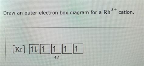
Table of Contents
Drawing Outer Electron Box Diagrams for Cations: A Comprehensive Guide
Understanding electron configurations is fundamental to chemistry. This guide delves into the process of drawing outer electron box diagrams, specifically for cations – positively charged ions formed by the loss of electrons. We'll cover the basics, explain the step-by-step process, explore various examples, and address common challenges.
Understanding Electron Configurations and Cations
Before diving into drawing diagrams, let's review some key concepts. An electron configuration describes the arrangement of electrons within an atom's electron shells and subshells. These configurations follow specific rules, primarily the Aufbau principle (filling orbitals from lowest to highest energy), Hund's rule (maximizing unpaired electrons within a subshell), and the Pauli exclusion principle (no two electrons can have the same four quantum numbers).
A cation is formed when a neutral atom loses one or more electrons. This loss typically occurs from the atom's outermost shell, also known as the valence shell. The number of electrons lost determines the cation's charge. For example, a sodium atom (Na) loses one electron to become a sodium cation (Na⁺), while a magnesium atom (Mg) loses two electrons to become a magnesium cation (Mg²⁺).
The outer electron box diagram, also known as an orbital box diagram or electron configuration diagram, visually represents the distribution of electrons in the valence shell. It uses boxes to represent orbitals and arrows to represent electrons, with upward and downward arrows indicating opposite electron spins.
Step-by-Step Guide to Drawing Outer Electron Box Diagrams for Cations
Here's a step-by-step guide to creating outer electron box diagrams for cations:
Step 1: Determine the neutral atom's electron configuration.
First, identify the element and determine its electron configuration. You can use the periodic table to find the atomic number (number of protons and electrons in a neutral atom) and then apply the rules mentioned earlier to fill the orbitals.
Step 2: Identify the valence electrons.
The valence electrons are the electrons in the outermost shell. These are the electrons involved in chemical bonding and are the ones lost when a cation forms. You can identify them by looking at the highest principal energy level (n) in the electron configuration.
Step 3: Determine the number of electrons lost.
The number of electrons lost equals the cation's charge. For example, a +1 charge means one electron lost, a +2 charge means two electrons lost, and so on. This information is crucial for accurately depicting the cation's electron configuration.
Step 4: Draw the outer electron box diagram for the cation.
Now, draw the boxes representing the orbitals in the valence shell. Remember that s subshells have one orbital, p subshells have three orbitals, and d subshells have five orbitals. Place the remaining valence electrons (after removing those lost) into the boxes, following Hund's rule and the Pauli exclusion principle.
Step 5: Indicate the cation's charge.
Finally, write the cation's symbol with its charge (e.g., Na⁺, Mg²⁺) next to the diagram to clearly indicate the ion represented.
Examples: Drawing Outer Electron Box Diagrams for Cations
Let's illustrate the process with several examples:
Example 1: Sodium cation (Na⁺)
- Neutral atom electron configuration: 1s²2s²2p⁶3s¹
- Valence electrons: 1 (in the 3s orbital)
- Electrons lost: 1 (because of the +1 charge)
- Outer electron box diagram:
Na⁺: 3s: [ ]
The 3s orbital, which originally contained one electron, is now empty.
Example 2: Magnesium cation (Mg²⁺)
- Neutral atom electron configuration: 1s²2s²2p⁶3s²
- Valence electrons: 2 (in the 3s orbital)
- Electrons lost: 2 (because of the +2 charge)
- Outer electron box diagram:
Mg²⁺: 3s: [ ]
Both electrons from the 3s orbital are removed.
Example 3: Aluminum cation (Al³⁺)
- Neutral atom electron configuration: 1s²2s²2p⁶3s²3p¹
- Valence electrons: 3 (two in 3s, one in 3p)
- Electrons lost: 3 (because of the +3 charge)
- Outer electron box diagram:
Al³⁺: 3s: [ ] 3p: [ ] [ ] [ ]
All three valence electrons are removed, leaving empty 3s and 3p orbitals.
Example 4: Iron(II) cation (Fe²⁺)
- Neutral atom electron configuration: [Ar] 3d⁶4s² (Note: We often use noble gas notation for brevity)
- Valence electrons: 8 (two in 4s, six in 3d – for transition metals, both 3d and 4s electrons are considered valence)
- Electrons lost: 2 (because of the +2 charge) Typically, transition metals lose 4s electrons before 3d electrons.
- Outer electron box diagram:
Fe²⁺: 3d: [↑↓][↑↓][↑↓][↑ ][ ] 4s: [ ]
The two 4s electrons are lost first.
Example 5: Copper(II) cation (Cu²⁺)
- Neutral atom electron configuration: [Ar] 3d¹⁰4s¹ (Anomalous configuration; remember exceptions exist!)
- Valence electrons: 11 (one in 4s, ten in 3d)
- Electrons lost: 2 (because of the +2 charge) In Cu²⁺, the one 4s electron and one 3d electron are lost.
- Outer electron box diagram:
Cu²⁺: 3d: [↑↓][↑↓][↑↓][↑↓][↑↓] 4s: [ ]
Addressing Common Challenges and Advanced Considerations
Drawing these diagrams becomes more complex with transition metals and other exceptions to the standard filling rules. Remember to carefully consider the electron configuration of the neutral atom before removing electrons to form the cation.
-
Transition Metals: Transition metals often exhibit multiple oxidation states, leading to different numbers of electrons lost and varying outer electron box diagrams for each cation. Always refer to the specific oxidation state provided.
-
Anomalous Electron Configurations: Some elements, such as chromium (Cr) and copper (Cu), have electron configurations that deviate from the expected pattern. Be sure to consult a reliable source for the correct electron configuration of the neutral atom before drawing the cation's diagram.
-
Lanthanides and Actinides: The electron configurations of these elements become significantly more complex, adding another layer of challenge to drawing accurate diagrams. However, the principles remain the same: determine the neutral atom's configuration, identify valence electrons, and remove the appropriate number of electrons based on the cation's charge.
-
Using Noble Gas Notation: For larger atoms, using noble gas notation (e.g., [Ar] for elements after Argon) simplifies the representation of the inner electron shells, focusing only on the valence electrons in the diagram.
Conclusion
Drawing outer electron box diagrams for cations is a valuable skill for understanding electron configurations and ionic bonding. By carefully following the steps outlined above and considering the specific challenges associated with different elements, you can accurately depict the arrangement of electrons in various cations. Remember to always consult reliable resources such as periodic tables and chemistry textbooks to confirm electron configurations and handle exceptions. Mastering this skill provides a solid foundation for further exploration in chemistry.
Latest Posts
Latest Posts
-
Which Revision Of The Sentence Uses Parallel Structure 2 4 3
Mar 09, 2025
-
Eating Soup That Has Been Time Temperature Abuse Can Result In
Mar 09, 2025
-
The Image Was Created Most Directly In Response To
Mar 09, 2025
-
Chapter 11 Summary To Kill A Mockingbird
Mar 09, 2025
-
Natural Language Processing Is Ai That
Mar 09, 2025
Related Post
Thank you for visiting our website which covers about Draw An Outer Electron Box Diagram For A Cation . We hope the information provided has been useful to you. Feel free to contact us if you have any questions or need further assistance. See you next time and don't miss to bookmark.
